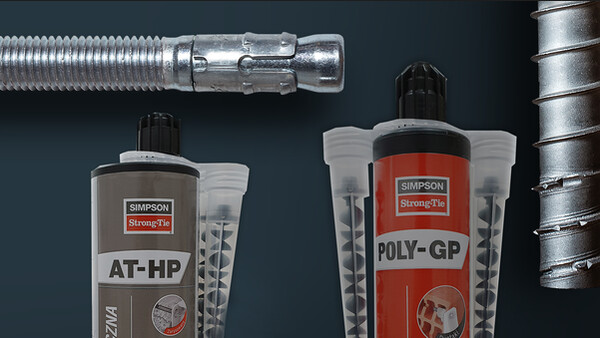

AT-HP PLUS
Resina para múltiples materiales con indicador de montaje
Esta resina de adhesión química AT-HP Plus abarca el 100 % de las aplicaciones habituales de mampostería maciza y hueca. Se puede utilizar sin riesgo en interior (COV A+) y garantiza una fijación fácil y eficaz gracias a una innovación exclusiva: el indicador de montaje Simpson Strong-Tie.
Marcado CE
DITE
Fuego
Interior
Exterior
Distancia al borde y entre ejes

Detalles de producto
Imagenes


Características
Materia
- Resina de metacrilato.
- Varilla roscada : acero electrocincado y acero inoxidable A4-70.
Ventajas
- Alto valor de adhesión en el hormigón y la mampostería.
- Muy buen comportamiento en perforación húmeda y/o mojada.
- Resistencia al fuego.
- 2 DITE para las varillas roscadas en el hormigón y la mampostería.
- 1 DITE para la colocación de varillas de hierro en el hormigón.
Aplicaciones
Soporte
- Hormigón, hormigón celular.
- Ladrillo hueco y macizo.
- Piedra sillar hueca y maciza.
Campos de aplicación
- Colocación de varillas de hierro en el hormigón.
- Fijación de vigas, escuadras de revestimiento de fachada.
- Fijación de vigas metálicas, grúas de puente.
- Fijación de barandillas, andamios.
Datos técnicos
Références
| Modelo | Product information | ||||
|---|---|---|---|---|---|
| Grey color | Beige color | Content [ml] | Weigth [kg] | Packaging qty [pcs] | |
| ATHP300PLUSG-FR | x | - | 300 | 0.575 | 12 |
| ATHP420PLUSG-FR | x | - | 420 | 0.828 | 12 |
Design resistance – Tension – NRd [kN] – hef = 8d – Carbon steel 5.8
| Modelo | Design resistance – hef = 8d – Carbon steel 5.8 | |||||||
|---|---|---|---|---|---|---|---|---|
| Tension - NRd [kN] | ||||||||
| Cracked concrete | Non-cracked concrete | |||||||
| C20/25 | C30/37 | C40/50 | C50/60 | C20/25 | C30/37 | C40/50 | C50/60 | |
| AT-HP PLUS + LMAS M8 | - | - | - | - | 10.7 | 12 | 12 | 12 |
| AT-HP PLUS + LMAS M10 | - | - | - | - | 15.9 | 17.8 | 19.3 | 19.3 |
| AT-HP PLUS + LMAS M12 | 8.4 | 8.8 | 9 | 9.2 | 21.7 | 24.3 | 26.7 | 28 |
| AT-HP PLUS + LMAS M16 | 15 | 15.6 | 16.1 | 16.4 | 34.3 | 38.4 | 42.2 | 44.6 |
| AT-HP PLUS + LMAS M20 | - | - | - | - | 50.2 | 56.3 | 61.8 | 65.3 |
| AT-HP PLUS + LMAS M24 | - | - | - | - | 67.5 | 75.6 | 83.1 | 87.8 |
Concrete :
1. The design loads have been calculated using the partial safety factors for resistances stated in ETA-approval(s). The loading figures are valid for unreinforced concrete and reinforced concrete with a rebar spacing s ≥ 15 cm (any diameter) or with a rebar spacing s ≥ 10 cm, if the rebar diameter is 10mm or smaller.
2. The figures for shear are based on a single anchor without influence of concrete edges. For anchorages close to edges (c ≤ max [10 hef; 60d]) the concrete edge failure shall be checked per ETAG 001, Annex C, design method A.
3. Concrete is considered non-cracked when the tensile stress within the concrete is\sigmaL +\sigmaR ≤ 0. In the absence of detailed verification\sigmaR = 3 N/mm² can be assumed (\sigmaL equals the tensile stress within the concrete induced by external loads, anchors loads included).
Design resistance – Tension – NRd [kN] – hef = 12d – Carbon steel 5.8
| Modelo | Design resistance – hef = 12d – Carbon steel 5.8 | |||||||
|---|---|---|---|---|---|---|---|---|
| Tension - NRd [kN] | ||||||||
| Cracked concrete | Non-cracked concrete | |||||||
| C20/25 | C30/37 | C40/50 | C50/60 | C20/25 | C30/37 | C40/50 | C50/60 | |
| AT-HP PLUS + LMAS M8 | - | - | - | - | 12 | 12 | 12 | 12 |
| AT-HP PLUS + LMAS M10 | - | - | - | - | 19.3 | 19.3 | 19.3 | 19.3 |
| AT-HP PLUS + LMAS M12 | 12.7 | 13.2 | 13.5 | 13.8 | 28 | 28 | 28 | 28 |
| AT-HP PLUS + LMAS M16 | 22.5 | 23.4 | 24.1 | 24.5 | 51.4 | 52.7 | 52.7 | 52.7 |
| AT-HP PLUS + LMAS M20 | - | - | - | - | 75.4 | 82 | 82 | 82 |
| AT-HP PLUS + LMAS M24 | - | - | - | - | 101.3 | 113.4 | 118 | 118 |
Concrete:
1. The design loads have been calculated using the partial safety factors for resistances stated in ETA-approval(s). The loading figures are valid for unreinforced concrete and reinforced concrete with a rebar spacing s ≥ 15 cm (any diameter) or with a rebar spacing s ≥ 10 cm, if the rebar diameter is 10mm or smaller.
2. The figures for shear are based on a single anchor without influence of concrete edges. For anchorages close to edges (c ≤ max [10 hef; 60d]) the concrete edge failure shall be checked per ETAG 001, Annex C, design method A.
3. Concrete is considered non-cracked when the tensile stress within the concrete is\sigmaL +\sigmaR ≤ 0. In the absence of detailed verification\sigmaR = 3 N/mm² can be assumed (\sigmaL equals the tensile stress within the concrete induced by external loads, anchors loads included).
Design resistance – Tension – NRd [kN] – hef = 8d – Stainless steel A4-70
| Modelo | Design resistance – hef = 8d – Stainless steel A4-70 | |||||||
|---|---|---|---|---|---|---|---|---|
| Tension - NRd [kN] | ||||||||
| Cracked concrete | Non-cracked concrete | |||||||
| C20/25 | C30/37 | C40/50 | C50/60 | C20/25 | C30/37 | C40/50 | C50/60 | |
| AT-HP PLUS + LMAS M8 | - | - | - | - | 10.7 | 12 | 13.2 | 13.9 |
| AT-HP PLUS + LMAS M10 | - | - | - | - | 15.9 | 17.8 | 19.6 | 20.7 |
| AT-HP PLUS + LMAS M12 | 8.4 | 8.8 | 9 | 9.2 | 21.7 | 24.3 | 26.7 | 28.2 |
| AT-HP PLUS + LMAS M16 | 15 | 15.6 | 16.1 | 16.4 | 34.3 | 38.4 | 42.2 | 44.6 |
| AT-HP PLUS + LMAS M20 | - | - | - | - | 50.2 | 56.3 | 61.8 | 65.3 |
| AT-HP PLUS + LMAS M24 | - | - | - | - | 67.5 | 75.6 | 83.1 | 87.8 |
Concrete :
1. The design loads have been calculated using the partial safety factors for resistances stated in ETA-approval(s). The loading figures are valid for unreinforced concrete and reinforced concrete with a rebar spacing s ≥ 15 cm (any diameter) or with a rebar spacing s ≥ 10 cm, if the rebar diameter is 10mm or smaller.
2. The figures for shear are based on a single anchor without influence of concrete edges. For anchorages close to edges (c ≤ max [10 hef; 60d]) the concrete edge failure shall be checked per ETAG 001, Annex C, design method A.
3. Concrete is considered non-cracked when the tensile stress within the concrete is\sigmaL +\sigmaR ≤ 0. In the absence of detailed verification\sigmaR = 3 N/mm² can be assumed (\sigmaL equals the tensile stress within the concrete induced by external loads, anchors loads included).
Design resistance – Tension – NRd [kN] – hef = 12d – Stainless steel A4-70
| Modelo | Design resistance – hef = 12d – Stainless steel A4-70 | |||||||
|---|---|---|---|---|---|---|---|---|
| Tension - NRd [kN] | ||||||||
| Cracked concrete | Non-cracked concrete | |||||||
| C20/25 | C30/37 | C40/50 | C50/60 | C20/25 | C30/37 | C40/50 | C50/60 | |
| AT-HP PLUS + LMAS M8 | - | - | - | - | 13.9 | 13.9 | 13.9 | 13.9 |
| AT-HP PLUS + LMAS M10 | - | - | - | - | 21.9 | 21.9 | 21.9 | 21.9 |
| AT-HP PLUS + LMAS M12 | 12.7 | 13.2 | 13.5 | 13.8 | 31.6 | 31.6 | 31.6 | 31.6 |
| AT-HP PLUS + LMAS M16 | 22.5 | 23.4 | 24.1 | 24.5 | 51.4 | 57.6 | 58.8 | 58.8 |
| AT-HP PLUS + LMAS M20 | - | - | - | - | 75.4 | 84.4 | 92 | 92 |
| AT-HP PLUS + LMAS M24 | - | - | - | - | 101.3 | 113.4 | 124.6 | 131.7 |
Concrete :
1. The design loads have been calculated using the partial safety factors for resistances stated in ETA-approval(s). The loading figures are valid for unreinforced concrete and reinforced concrete with a rebar spacing s ≥ 15 cm (any diameter) or with a rebar spacing s ≥ 10 cm, if the rebar diameter is 10mm or smaller.
2. The figures for shear are based on a single anchor without influence of concrete edges. For anchorages close to edges (c ≤ max [10 hef; 60d]) the concrete edge failure shall be checked per ETAG 001, Annex C, design method A.
3. Concrete is considered non-cracked when the tensile stress within the concrete is\sigmaL +\sigmaR ≤ 0. In the absence of detailed verification\sigmaR = 3 N/mm² can be assumed (\sigmaL equals the tensile stress within the concrete induced by external loads, anchors loads included).
Design resistance – Shear – VRd [kN] – hef = 8d – Carbon steel 5.8
| Modelo | Design resistance – hef = 8d – Carbon steel 5.8 | |||||||
|---|---|---|---|---|---|---|---|---|
| Shear - VRd [kN] | ||||||||
| Cracked concrete | Non-cracked concrete | |||||||
| C20/25 | C30/37 | C40/50 | C50/60 | C20/25 | C30/37 | C40/50 | C50/60 | |
| AT-HP PLUS + LMAS M8 | - | - | - | - | 7.2 | 7.2 | 7.2 | 7.2 |
| AT-HP PLUS + LMAS M10 | - | - | - | - | 12 | 12 | 12 | 12 |
| AT-HP PLUS + LMAS M12 | 16.8 | 16.8 | 16.8 | 16.8 | 16.8 | 16.8 | 16.8 | 16.8 |
| AT-HP PLUS + LMAS M16 | 30 | 31.2 | 31.2 | 31.2 | 31.2 | 31.2 | 31.2 | 31.2 |
| AT-HP PLUS + LMAS M20 | - | - | - | - | 48.8 | 48.8 | 48.8 | 48.8 |
| AT-HP PLUS + LMAS M24 | - | - | - | - | 70.4 | 70.4 | 70.4 | 70.4 |
Concrete :
1. The design loads have been calculated using the partial safety factors for resistances stated in ETA-approval(s). The loading figures are valid for unreinforced concrete and reinforced concrete with a rebar spacing s ≥ 15 cm (any diameter) or with a rebar spacing s ≥ 10 cm, if the rebar diameter is 10mm or smaller.
2. The figures for shear are based on a single anchor without influence of concrete edges. For anchorages close to edges (c ≤ max [10 hef; 60d]) the concrete edge failure shall be checked per ETAG 001, Annex C, design method A.
3. Concrete is considered non-cracked when the tensile stress within the concrete is\sigmaL +\sigmaR ≤ 0. In the absence of detailed verification\sigmaR = 3 N/mm² can be assumed (\sigmaL equals the tensile stress within the concrete induced by external loads, anchors loads included).
Design resistance – Shear – VRd [kN] – hef = 12d – Carbon steel 5.8
| Modelo | Design resistance – hef = 12d – Carbon steel 5.8 | |||||||
|---|---|---|---|---|---|---|---|---|
| Shear - VRd [kN] | ||||||||
| Cracked concrete | Non-cracked concrete | |||||||
| C20/25 | C30/37 | C40/50 | C50/60 | C20/25 | C30/37 | C40/50 | C50/60 | |
| AT-HP PLUS + LMAS M8 | - | - | - | - | 7.2 | 7.2 | 7.2 | 7.2 |
| AT-HP PLUS + LMAS M10 | - | - | - | - | 12 | 12 | 12 | 12 |
| AT-HP PLUS + LMAS M12 | 16.8 | 16.8 | 16.8 | 16.8 | 16.8 | 16.8 | 16.8 | 16.8 |
| AT-HP PLUS + LMAS M16 | 31.2 | 31.2 | 31.2 | 31.2 | 31.2 | 31.2 | 31.2 | 31.2 |
| AT-HP PLUS + LMAS M20 | - | - | - | - | 48.8 | 48.8 | 48.8 | 48.8 |
| AT-HP PLUS + LMAS M24 | - | - | - | - | 70.4 | 70.4 | 70.4 | 70.4 |
Concrete :
1. The design loads have been calculated using the partial safety factors for resistances stated in ETA-approval(s). The loading figures are valid for unreinforced concrete and reinforced concrete with a rebar spacing s ≥ 15 cm (any diameter) or with a rebar spacing s ≥ 10 cm, if the rebar diameter is 10mm or smaller.
2. The figures for shear are based on a single anchor without influence of concrete edges. For anchorages close to edges (c ≤ max [10 hef; 60d]) the concrete edge failure shall be checked per ETAG 001, Annex C, design method A.
3. Concrete is considered non-cracked when the tensile stress within the concrete is\sigmaL +\sigmaR ≤ 0. In the absence of detailed verification\sigmaR = 3 N/mm² can be assumed (\sigmaL equals the tensile stress within the concrete induced by external loads, anchors loads included).
Design resistance – Shear – VRd [kN] – hef = 8d – Stainless steel A4-70
| Modelo | Design resistance – hef = 8d – Stainless steel A4-70 | |||||||
|---|---|---|---|---|---|---|---|---|
| Shear - VRd [kN] | ||||||||
| Cracked concrete | Non-cracked concrete | |||||||
| C20/25 | C30/37 | C40/50 | C50/60 | C20/25 | C30/37 | C40/50 | C50/60 | |
| AT-HP PLUS + LMAS M8 | - | - | - | - | 8.3 | 8.3 | 8.3 | 8.3 |
| AT-HP PLUS + LMAS M10 | - | - | - | - | 12.8 | 12.8 | 12.8 | 12.8 |
| AT-HP PLUS + LMAS M12 | 16.9 | 17.6 | 18.1 | 18.4 | 19.2 | 19.2 | 19.2 | 19.2 |
| AT-HP PLUS + LMAS M16 | 30 | 31.2 | 32.1 | 32.7 | 35.3 | 35.3 | 35.3 | 35.3 |
| AT-HP PLUS + LMAS M20 | - | - | - | - | 55.1 | 55.1 | 55.1 | 55.1 |
| AT-HP PLUS + LMAS M24 | - | - | - | - | 79.5 | 79.5 | 79.5 | 79.5 |
Concrete :
1. The design loads have been calculated using the partial safety factors for resistances stated in ETA-approval(s). The loading figures are valid for unreinforced concrete and reinforced concrete with a rebar spacing s ≥ 15 cm (any diameter) or with a rebar spacing s ≥ 10 cm, if the rebar diameter is 10mm or smaller.
2. The figures for shear are based on a single anchor without influence of concrete edges. For anchorages close to edges (c ≤ max [10 hef; 60d]) the concrete edge failure shall be checked per ETAG 001, Annex C, design method A.
3. Concrete is considered non-cracked when the tensile stress within the concrete is\sigmaL +\sigmaR ≤ 0. In the absence of detailed verification\sigmaR = 3 N/mm² can be assumed (\sigmaL equals the tensile stress within the concrete induced by external loads, anchors loads included).
Design resistance – Shear – VRd [kN] – hef = 12d – Stainless steel A4-70
| Modelo | Design resistance – hef = 12d – Stainless steel A4-70 | |||||||
|---|---|---|---|---|---|---|---|---|
| Shear - VRd [kN] | ||||||||
| Cracked concrete | Non-cracked concrete | |||||||
| C20/25 | C30/37 | C40/50 | C50/60 | C20/25 | C30/37 | C40/50 | C50/60 | |
| AT-HP PLUS + LMAS M8 | - | - | - | - | 8.3 | 8.3 | 8.3 | 8.3 |
| AT-HP PLUS + LMAS M10 | - | - | - | - | 12.8 | 12.8 | 12.8 | 12.8 |
| AT-HP PLUS + LMAS M12 | 19.2 | 19.2 | 19.2 | 19.2 | 19.2 | 19.2 | 19.2 | 19.2 |
| AT-HP PLUS + LMAS M16 | 35.3 | 35.3 | 35.3 | 35.3 | 35.3 | 35.3 | 35.3 | 35.3 |
| AT-HP PLUS + LMAS M20 | - | - | - | - | 55.1 | 55.1 | 55.1 | 55.1 |
| AT-HP PLUS + LMAS M24 | - | - | - | - | 79.5 | 79.5 | 79.5 | 79.5 |
Concrete :
1. The design loads have been calculated using the partial safety factors for resistances stated in ETA-approval(s). The loading figures are valid for unreinforced concrete and reinforced concrete with a rebar spacing s ≥ 15 cm (any diameter) or with a rebar spacing s ≥ 10 cm, if the rebar diameter is 10mm or smaller.
2. The figures for shear are based on a single anchor without influence of concrete edges. For anchorages close to edges (c ≤ max [10 hef; 60d]) the concrete edge failure shall be checked per ETAG 001, Annex C, design method A.
3. Concrete is considered non-cracked when the tensile stress within the concrete is\sigmaL +\sigmaR ≤ 0. In the absence of detailed verification\sigmaR = 3 N/mm² can be assumed (\sigmaL equals the tensile stress within the concrete induced by external loads, anchors loads included).
Design resistance – Bending moment – MRd [Nm] – Concrete
| Modelo | Design resistance – Bending moment – MRd [Nm] | |
|---|---|---|
| Carbon steel 5.8 | Stainless steel A4-70 | |
| AT-HP PLUS + LMAS M8 | 15.2 | 16.7 |
| AT-HP PLUS + LMAS M10 | 29.6 | 34 |
| AT-HP PLUS + LMAS M12 | 52.8 | 59 |
| AT-HP PLUS + LMAS M16 | 133.6 | 149.4 |
| AT-HP PLUS + LMAS M20 | 260.8 | 291 |
| AT-HP PLUS + LMAS M24 | 448.8 | 502.6 |
Concrete :
1. The design loads have been calculated using the partial safety factors for resistances stated in ETA-approval(s). The loading figures are valid for unreinforced concrete and reinforced concrete with a rebar spacing s ≥ 15 cm (any diameter) or with a rebar spacing s ≥ 10 cm, if the rebar diameter is 10mm or smaller.
2. The figures for shear are based on a single anchor without influence of concrete edges. For anchorages close to edges (c ≤ max [10 hef; 60d]) the concrete edge failure shall be checked per ETAG 001, Annex C, design method A.
3. Concrete is considered non-cracked when the tensile stress within the concrete is\sigmaL +\sigmaR ≤ 0. In the absence of detailed verification\sigmaR = 3 N/mm² can be assumed (\sigmaL equals the tensile stress within the concrete induced by external loads, anchors loads included).
Design resistance – Tension – NRd [kN] – Rebar
| Modelo | Design resistance – NRd – Carbon steel 5.8 [kN] | |||||||
|---|---|---|---|---|---|---|---|---|
| Non-cracked concrete | ||||||||
| hef = 8d | hef = 12d | |||||||
| C20/25 | C30/37 | C40/50 | C50/60 | C20/25 | C30/37 | C40/50 | C50/60 | |
| AT-HP PLUS + Ø8 | 6.3 | 7 | 7.7 | 8.1 | 9.4 | 10.5 | 11.5 | 12.2 |
| AT-HP PLUS + Ø10 | 10.5 | 11.7 | 12.9 | 13.6 | 15.7 | 17.6 | 19.3 | 20.4 |
| AT-HP PLUS + Ø12 | 14.1 | 15.8 | 17.3 | 18.3 | 21.1 | 23.6 | 26 | 27.4 |
| AT-HP PLUS + Ø14 | 19.1 | 21.4 | 23.6 | 24.9 | 28.7 | 32.2 | 35.3 | 37.3 |
| AT-HP PLUS + Ø16 | 23.2 | 26 | 28.6 | 34.8 | 34.8 | 39 | 42.8 | 52.2 |
| AT-HP PLUS + Ø20 | 36.3 | 40.6 | 44.6 | 47.2 | 54.4 | 61 | 66.9 | 70.8 |
| AT-HP PLUS + Ø25 | 52.3 | 58.6 | 64.4 | 68 | 78.5 | 87.9 | 96.6 | 102.1 |
Design resistance – Shear – VRd [kN] – Rebar
| Modelo | Design resistance – VRd – Carbon steel 5.8 [kN] | |||||||
|---|---|---|---|---|---|---|---|---|
| Non-cracked concrete | ||||||||
| hef = 8d | hef = 12d | |||||||
| C20/25 | C30/37 | C40/50 | C50/60 | C20/25 | C30/37 | C40/50 | C50/60 | |
| AT-HP PLUS + Ø8 | 9.3 | 9.3 | 9.3 | 9.3 | 9.3 | 9.3 | 9.3 | 9.3 |
| AT-HP PLUS + Ø10 | 14.7 | 14.7 | 14.7 | 14.7 | 14.7 | 14.7 | 14.7 | 14.7 |
| AT-HP PLUS + Ø12 | 20.7 | 20.7 | 20.7 | 20.7 | 20.7 | 20.7 | 20.7 | 20.7 |
| AT-HP PLUS + Ø14 | 28 | 28 | 28 | 28 | 28 | 28 | 28 | 28 |
| AT-HP PLUS + Ø16 | 36.7 | 36.7 | 36.7 | 36.7 | 36.7 | 36.7 | 36.7 | 36.7 |
| AT-HP PLUS + Ø20 | 57.3 | 57.3 | 57.3 | 57.3 | 57.3 | 57.3 | 57.3 | 57.3 |
| AT-HP PLUS + Ø25 | 90 | 90 | 90 | 90 | 90 | 90 | 90 | 90 |
Design resistance – Bending moment – MRd [Nm] – Rebar
| Modelo | Design resistance – Bending moment – MRd [Nm] |
|---|---|
| AT-HP PLUS + Ø8 | 22 |
| AT-HP PLUS + Ø10 | 43.3 |
| AT-HP PLUS + Ø12 | 74.7 |
| AT-HP PLUS + Ø14 | 118.7 |
| AT-HP PLUS + Ø16 | 176.7 |
| AT-HP PLUS + Ø20 | 345.3 |
| AT-HP PLUS + Ø25 | 674.7 |
Instalación
Montaje
Tiempos de montaje
| Temperatura [°C] | -5°C | 0°C | 5°C | 10°C | 20°C | 30°C |
| Tiempo de curado | 45min | 15min | 12min | 9min | 4min | 1min |
| Tiempo hasta la solicitación | 9h | 4h | 1h30 | 60min | 30min | 20min |
Méthodes de perçage
| Brique pleine/Béton | perçage à percussion |
| Brique creuse | perçage rotatif |
| Béton cellulaire | perçage à percussion |

Perfore.

Cepille.

Introduzca un tamiz.

Llene el orificio desde el fondo hacia el exterior, inyectando con la boquilla una dosis de producto en cada movimiento.

Inserte la varilla girándola lentamente.

Fije el anclaje una vez haya transcurrido el tiempo de solicitación.

Perfore.

Limpie el orificio con un cepillo e insuflando aire, según lo especificado en el cartucho.

Llene entre 1/2 y 2/3 del orificio desde el fondo hacia el exterior, inyectando cada vez una dosis de producto con la boquilla.

Introduzca la varilla LMAS, girándola lentamente de izquierda a derecha. Ajústela.

Fije el anclaje una vez haya transcurrido el tiempo de solicitación.
Installation parameters – Concrete
| Modelo | Installation parameters - Concrete | |||||
|---|---|---|---|---|---|---|
| Ø drilling [d0] [mm] | Max. fixture hole Ø [df] [mm] | Drilling depth (8d) [h0=hef=8d] [mm] | Drilling depth (12d) [h0=hef=12d] [mm] | Wrench size [SW] | Installation torque [Tinst] [Nm] | |
| AT-HP PLUS + LMAS M8 | 10 | 9 | 64 | 96 | 13 | 10 |
| AT-HP PLUS + LMAS M10 | 12 | 12 | 80 | 120 | 17 | 20 |
| AT-HP PLUS + LMAS M12 | 14 | 14 | 96 | 144 | 19 | 30 |
| AT-HP PLUS + LMAS M16 | 18 | 18 | 128 | 192 | 24 | 60 |
| AT-HP PLUS + LMAS M20 | 24 | 22 | 160 | 240 | 30 | 90 |
| AT-HP PLUS + LMAS M24 | 28 | 26 | 192 | 288 | 36 | 140 |
Spacing, edge distances and member thickness – Concrete
| Modelo | Spacing, edge distance and member thickness - Concrete | |||||||||
|---|---|---|---|---|---|---|---|---|---|---|
| Effective embedment depth (8d) [hef,8d] [mm] | Characteristic spacing for hef,8d [Scr,N] [mm] | Characteristic edge distance for hef,8d [ccr,N] [mm] | Min. member thickness for hef,8d [hmin] [mm] | Effective embedment depth (12d) [hef,12d] [mm] | Characteristic spacing for hef,12d [Scr,N] [mm] | Characteristic edge distance for hef,12d [ccr,N] [mm] | Min. member thickness for hef,12d [hmin] [mm] | Min. spacing [Smin] [mm] | Min. edge distance [Cmin] [mm] | |
| AT-HP PLUS + LMAS M8 | 64 | 192 | 96 | 100 | 96 | 288 | 144 | 100 | 40 | 40 |
| AT-HP PLUS + LMAS M10 | 80 | 240 | 120 | 110 | 120 | 360 | 180 | 150 | 50 | 50 |
| AT-HP PLUS + LMAS M12 | 96 | 288 | 144 | 126 | 144 | 432 | 216 | 174 | 60 | 60 |
| AT-HP PLUS + LMAS M16 | 128 | 384 | 192 | 158 | 192 | 576 | 288 | 222 | 80 | 80 |
| AT-HP PLUS + LMAS M20 | 160 | 480 | 240 | 190 | 240 | 720 | 360 | 270 | 100 | 100 |
| AT-HP PLUS + LMAS M24 | 192 | 576 | 288 | 222 | 288 | 864 | 432 | 318 | 120 | 120 |
Installation parameters – Rebar
| Modelo | Installation parameters - Rebar | ||
|---|---|---|---|
| Ø drilling [d0] [mm] | Drilling depth (8d) [h0=hef=8d] [mm] | Drilling depth (12d) [h0=hef=12d] [mm] | |
| AT-HP PLUS + Ø8 | 12 | 64 | 96 |
| AT-HP PLUS + Ø10 | 14 | 80 | 120 |
| AT-HP PLUS + Ø12 | 16 | 96 | 144 |
| AT-HP PLUS + Ø14 | 18 | 112 | 168 |
| AT-HP PLUS + Ø16 | 20 | 128 | 192 |
| AT-HP PLUS + Ø20 | 25 | 160 | 240 |
| AT-HP PLUS + Ø25 | 32 | 200 | 300 |
Spacing, edge distances and member thickness – Rebar
| Modelo | Spacing, edge distance and member thickness - Rebar | |||||||||
|---|---|---|---|---|---|---|---|---|---|---|
| Effective embedment depth (8d) [hef,8d] [mm] | Characteristic spacing for hef,8d [Scr,N] [mm] | Characteristic edge distance for hef,8d [ccr,N] [mm] | Min. member thickness for hef,8d [hmin] [mm] | Effective embedment depth (12d) [hef,12d] [mm] | Characteristic spacing for hef,12d [Scr,N] [mm] | Characteristic edge distance for hef,12d [ccr,N] [mm] | Min. member thickness for hef,12d [hmin] [mm] | Min. spacing [Smin] [mm] | Min. edge distance [Cmin] [mm] | |
| AT-HP PLUS + Ø8 | 64 | 192 | 96 | 100 | 96 | 288 | 144 | 100 | 40 | 40 |
| AT-HP PLUS + Ø10 | 80 | 240 | 120 | 110 | 120 | 360 | 180 | 150 | 50 | 50 |
| AT-HP PLUS + Ø12 | 96 | 288 | 144 | 126 | 144 | 432 | 216 | 174 | 60 | 60 |
| AT-HP PLUS + Ø14 | 112 | 336 | 168 | 148 | 168 | 504 | 252 | 204 | 70 | 70 |
| AT-HP PLUS + Ø16 | 128 | 384 | 192 | 168 | 192 | 576 | 288 | 232 | 80 | 80 |
| AT-HP PLUS + Ø20 | 160 | 480 | 240 | 210 | 240 | 720 | 360 | 290 | 100 | 100 |
| AT-HP PLUS + Ø25 | 200 | 600 | 300 | 264 | 300 | 900 | 450 | 364 | 125 | 125 |
Certificación
Idoneidad Técnica Europeo (ETA)
Ficha de datos de seguridad (MSDS)
strongtie-france-at-hp-plus-spanish.pdf
(210.08 KB)
