
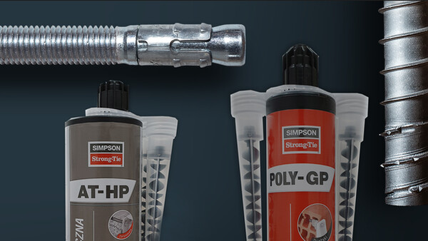

VT-HP®
Sistema de inyección para hormigón
Marcado CE
DITE
Utilizable en medio húmedo
Resistencia a choques de corte duración (terremoto, explosión...)
Interior
Exterior
Fuego R 180

Detalles de producto
Imagenes


Características
Water Regulations Advisory Scheme LTD. (WRAS) Material Approval
wras-vthp.pdf
(68.11 KB)
Datos técnicos
Referencia
| Modelo | Informacion de producto | ||||
|---|---|---|---|---|---|
| Gris | Beige | Contenido [ml] | Peso [kg] | Qdad. [pcs] | |
| VTHP420-EU | x | - | 420 | 0.796 | 12 |
Design resistance – Tension – NRd [kN] – hef = 8d – Carbon steel 5.8
| Modelo | Design resistance – hef = 8d – Carbon steel 5.8 | |||||||
|---|---|---|---|---|---|---|---|---|
| Tension - NRd [kN] | ||||||||
| Cracked concrete | Non-cracked concrete | |||||||
| C20/25 | C30/37 | C40/50 | C50/60 | C20/25 | C30/37 | C40/50 | C50/60 | |
| VT-HP + LMAS M8 | 4.3 | 4.5 | 4.6 | 4.7 | 10.7 | 11.1 | 11.6 | 11.8 |
| VT-HP + LMAS M10 | 7 | 7.3 | 7.5 | 7.7 | 16.7 | 17.4 | 18.1 | 18.4 |
| VT-HP + LMAS M12 | 11.1 | 11.5 | 11.9 | 12.2 | 24.1 | 25.1 | 26 | 26.5 |
| VT-HP + LMAS M16 | 19.6 | 20.4 | 21.2 | 21.6 | 40.6 | 44.6 | 46.3 | 47.2 |
| VT-HP + LMAS M20 | 30.7 | 31.9 | 33.2 | 33.8 | 56.8 | 69 | 72.3 | 73.7 |
| VT-HP + LMAS M24 | 44.2 | 46 | 47.7 | 48.6 | 74.6 | 90.8 | 95.5 | 97.3 |
| VT-HP + LMAS M27 | 63.5 | 68.8 | 71.4 | 72.7 | 89.1 | 105.8 | 109.9 | 111.9 |
| VT-HP + LMAS M30 | 74.4 | 84.9 | 88.2 | 89.8 | 104.3 | 117.6 | 122.1 | 124.3 |
Concrete :
1. The design loads have been calculated using the partial safety factors for resistances stated in ETA-approval(s). The loading figures are valid for unreinforced concrete and reinforced concrete with a rebar spacing s ≥ 15 cm (any diameter) or with a rebar spacing s ≥ 10 cm, if the rebar diameter is 10mm or smaller.
2. The figures for shear are based on a single anchor without influence of concrete edges. For anchorages close to edges (c ≤ max [10 hef; 60d]) the concrete edge failure shall be checked per ETAG 001, Annex C, design method A.
3. Concrete is considered non-cracked when the tensile stress within the concrete is\sigmaL +\sigmaR ≤ 0. In the absence of detailed verification\sigmaR = 3 N/mm² can be assumed (\sigmaL equals the tensile stress within the concrete induced by external loads, anchors loads included).
Design resistance – Tension – NRd [kN] – hef = 12d – Carbon steel 5.8
| Modelo | Design resistance – hef = 12d – Carbon steel 5.8 | |||||||
|---|---|---|---|---|---|---|---|---|
| Tension - NRd [kN] | ||||||||
| Cracked concrete | Non-cracked concrete | |||||||
| C20/25 | C30/37 | C40/50 | C50/60 | C20/25 | C30/37 | C40/50 | C50/60 | |
| VT-HP + LMAS M8 | 6.4 | 6.7 | 6.9 | 7.1 | 12 | 12 | 12 | 12 |
| VT-HP + LMAS M10 | 10.5 | 10.9 | 11.3 | 11.5 | 19.3 | 19.3 | 19.3 | 19.3 |
| VT-HP + LMAS M12 | 16.6 | 17.2 | 17.9 | 18.2 | 28 | 28 | 28 | 28 |
| VT-HP + LMAS M16 | 29.5 | 30.7 | 31.8 | 32.4 | 52 | 52 | 52 | 52 |
| VT-HP + LMAS M20 | 46.1 | 47.9 | 49.7 | 50.7 | 81.3 | 81.3 | 81.3 | 81.3 |
| VT-HP + LMAS M24 | 66.3 | 69 | 71.6 | 72.9 | 117.3 | 117.3 | 117.3 | 117.3 |
| VT-HP + LMAS M27 | 99.2 | 103.2 | 107.1 | 109.1 | 152.6 | 153.3 | 153.3 | 153.3 |
| VT-HP + LMAS M30 | 122.5 | 127.4 | 132.3 | 134.7 | 169.6 | 176.3 | 183.1 | 186.5 |
Concrete :
1. The design loads have been calculated using the partial safety factors for resistances stated in ETA-approval(s). The loading figures are valid for unreinforced concrete and reinforced concrete with a rebar spacing s ≥ 15 cm (any diameter) or with a rebar spacing s ≥ 10 cm, if the rebar diameter is 10mm or smaller.
2. The figures for shear are based on a single anchor without influence of concrete edges. For anchorages close to edges (c ≤ max [10 hef; 60d]) the concrete edge failure shall be checked per ETAG 001, Annex C, design method A.
3. Concrete is considered non-cracked when the tensile stress within the concrete is\sigmaL +\sigmaR ≤ 0. In the absence of detailed verification\sigmaR = 3 N/mm² can be assumed (\sigmaL equals the tensile stress within the concrete induced by external loads, anchors loads included).
Design resistance – Tension – NRd [kN] – hef = 8d – Stainless steel
| Modelo | Design resistance – hef = 8d – Stainless steel | |||||||
|---|---|---|---|---|---|---|---|---|
| Tension - NRd [kN] | ||||||||
| Cracked concrete | Non-cracked concrete | |||||||
| C20/25 | C30/37 | C40/50 | C50/60 | C20/25 | C30/37 | C40/50 | C50/60 | |
| VT-HP + LMAS M8 | 4.3 | 4.5 | 4.6 | 4.7 | 10.7 | 11.1 | 11.6 | 11.8 |
| VT-HP + LMAS M10 | 7 | 7.3 | 7.5 | 7.7 | 16.7 | 17.4 | 18.1 | 18.4 |
| VT-HP + LMAS M12 | 11.1 | 11.5 | 11.9 | 12.2 | 24.1 | 25.1 | 26 | 26.5 |
| VT-HP + LMAS M16 | 19.6 | 20.4 | 21.2 | 21.6 | 40.6 | 44.6 | 46.3 | 47.2 |
| VT-HP + LMAS M20 | 30.7 | 31.9 | 33.2 | 60.8 | 56.8 | 69 | 72.3 | 73.7 |
| VT-HP + LMAS M24 | 44.2 | 46 | 47.7 | 48.6 | 74.6 | 90.8 | 95.5 | 97.3 |
| VT-HP + LMAS M27 | 63.5 | 68.8 | 71.4 | 72.7 | 80.4 | 80.4 | 80.4 | 80.4 |
| VT-HP + LMAS M30 | 74.4 | 84.9 | 88.2 | 89.8 | 98.3 | 98.3 | 98.3 | 98.3 |
Threaded rod type A4-70 for M≤24 and A4-50 for M>24
Concrete :
1. The design loads have been calculated using the partial safety factors for resistances stated in ETA-approval(s). The loading figures are valid for unreinforced concrete and reinforced concrete with a rebar spacing s ≥ 15 cm (any diameter) or with a rebar spacing s ≥ 10 cm, if the rebar diameter is 10mm or smaller.
2. The figures for shear are based on a single anchor without influence of concrete edges. For anchorages close to edges (c ≤ max [10 hef; 60d]) the concrete edge failure shall be checked per ETAG 001, Annex C, design method A.
3. Concrete is considered non-cracked when the tensile stress within the concrete is\sigmaL +\sigmaR ≤ 0. In the absence of detailed verification\sigmaR = 3 N/mm² can be assumed (\sigmaL equals the tensile stress within the concrete induced by external loads, anchors loads included).
Design resistance – Tension – NRd [kN] – hef = 12d – Stainless steel
| Modelo | Design resistance – hef = 12d – Stainless steel | |||||||
|---|---|---|---|---|---|---|---|---|
| Tension - NRd [kN] | ||||||||
| Cracked concrete | Non-cracked concrete | |||||||
| C20/25 | C30/37 | C40/50 | C50/60 | C20/25 | C30/37 | C40/50 | C50/60 | |
| VT-HP + LMAS M8 | 6.4 | 6.7 | 6.9 | 7.1 | 13.9 | 13.9 | 13.9 | 13.9 |
| VT-HP + LMAS M10 | 10.5 | 10.9 | 11.3 | 11.5 | 21.9 | 21.9 | 21.9 | 21.9 |
| VT-HP + LMAS M12 | 16.6 | 17.2 | 17.9 | 18.2 | 31.6 | 31.6 | 31.6 | 31.6 |
| VT-HP + LMAS M16 | 29.5 | 30.7 | 31.8 | 32.4 | 58.8 | 58.8 | 58.8 | 58.8 |
| VT-HP + LMAS M20 | 46.1 | 47.9 | 49.7 | 91.2 | 91.4 | 91.4 | 91.4 | 91.4 |
| VT-HP + LMAS M24 | 66.3 | 69 | 71.6 | 72.9 | 132.1 | 132.1 | 132.1 | 132.1 |
| VT-HP + LMAS M27 | 80.4 | 80.4 | 80.4 | 80.4 | 80.4 | 80.4 | 80.4 | 80.4 |
| VT-HP + LMAS M30 | 98.3 | 98.3 | 98.3 | 98.3 | 98.3 | 98.3 | 98.3 | 98.3 |
Threaded rod type A4-70 for M≤24 and A4-50 for M>24
Concrete :
1. The design loads have been calculated using the partial safety factors for resistances stated in ETA-approval(s). The loading figures are valid for unreinforced concrete and reinforced concrete with a rebar spacing s ≥ 15 cm (any diameter) or with a rebar spacing s ≥ 10 cm, if the rebar diameter is 10mm or smaller.
2. The figures for shear are based on a single anchor without influence of concrete edges. For anchorages close to edges (c ≤ max [10 hef; 60d]) the concrete edge failure shall be checked per ETAG 001, Annex C, design method A.
3. Concrete is considered non-cracked when the tensile stress within the concrete is\sigmaL +\sigmaR ≤ 0. In the absence of detailed verification\sigmaR = 3 N/mm² can be assumed (\sigmaL equals the tensile stress within the concrete induced by external loads, anchors loads included).
Design resistance – Shear – VRd [kN] – hef = 8d – Carbon steel 5.8
| Modelo | Design resistance – hef = 8d – Carbon steel 5.8 | |||||||
|---|---|---|---|---|---|---|---|---|
| Shear - VRd [kN] | ||||||||
| Cracked concrete | Non-cracked concrete | |||||||
| C20/25 | C30/37 | C40/50 | C50/60 | C20/25 | C30/37 | C40/50 | C50/60 | |
| VT-HP + LMAS M8 | 7.2 | 7.2 | 7.2 | 7.2 | 7.2 | 7.2 | 7.2 | 7.2 |
| VT-HP + LMAS M10 | 12 | 12 | 12 | 12 | 12 | 12 | 12 | 12 |
| VT-HP + LMAS M12 | 16.8 | 16.8 | 16.8 | 16.8 | 16.8 | 16.8 | 16.8 | 16.8 |
| VT-HP + LMAS M16 | 31.2 | 31.2 | 31.2 | 31.2 | 31.2 | 31.2 | 31.2 | 31.2 |
| VT-HP + LMAS M20 | 48.8 | 48.8 | 48.8 | 48.8 | 48.8 | 48.8 | 48.8 | 48.8 |
| VT-HP + LMAS M24 | 70.4 | 70.4 | 70.4 | 70.4 | 70.4 | 70.4 | 70.4 | 70.4 |
| VT-HP + LMAS M27 | 92 | 92 | 92 | 92 | 92 | 92 | 92 | 92 |
| VT-HP + LMAS M30 | 112 | 112 | 112 | 112 | 112 | 112 | 112 | 112 |
Concrete :
1. The design loads have been calculated using the partial safety factors for resistances stated in ETA-approval(s). The loading figures are valid for unreinforced concrete and reinforced concrete with a rebar spacing s ≥ 15 cm (any diameter) or with a rebar spacing s ≥ 10 cm, if the rebar diameter is 10mm or smaller.
2. The figures for shear are based on a single anchor without influence of concrete edges. For anchorages close to edges (c ≤ max [10 hef; 60d]) the concrete edge failure shall be checked per ETAG 001, Annex C, design method A.
3. Concrete is considered non-cracked when the tensile stress within the concrete is\sigmaL +\sigmaR ≤ 0. In the absence of detailed verification\sigmaR = 3 N/mm² can be assumed (\sigmaL equals the tensile stress within the concrete induced by external loads, anchors loads included).
Design resistance – Shear – VRd [kN] – hef = 12d – Carbon steel 5.8
| Modelo | Design resistance – hef = 12d – Carbon steel 5.8 | |||||||
|---|---|---|---|---|---|---|---|---|
| Shear - VRd [kN] | ||||||||
| Cracked concrete | Non-cracked concrete | |||||||
| C20/25 | C30/37 | C40/50 | C50/60 | C20/25 | C30/37 | C40/50 | C50/60 | |
| VT-HP + LMAS M8 | 7.2 | 7.2 | 7.2 | 7.2 | 7.2 | 7.2 | 7.2 | 7.2 |
| VT-HP + LMAS M10 | 12 | 12 | 12 | 12 | 12 | 12 | 12 | 12 |
| VT-HP + LMAS M12 | 16.8 | 16.8 | 16.8 | 16.8 | 16.8 | 16.8 | 16.8 | 16.8 |
| VT-HP + LMAS M16 | 31.2 | 31.2 | 31.2 | 31.2 | 31.2 | 31.2 | 31.2 | 31.2 |
| VT-HP + LMAS M20 | 48.8 | 48.8 | 48.8 | 48.8 | 48.8 | 48.8 | 48.8 | 48.8 |
| VT-HP + LMAS M24 | 70.4 | 70.4 | 70.4 | 70.4 | 70.4 | 70.4 | 70.4 | 70.4 |
| VT-HP + LMAS M27 | 92 | 92 | 92 | 92 | 92 | 92 | 92 | 92 |
| VT-HP + LMAS M30 | 112 | 112 | 112 | 112 | 112 | 112 | 112 | 112 |
Concrete :
1. The design loads have been calculated using the partial safety factors for resistances stated in ETA-approval(s). The loading figures are valid for unreinforced concrete and reinforced concrete with a rebar spacing s ≥ 15 cm (any diameter) or with a rebar spacing s ≥ 10 cm, if the rebar diameter is 10mm or smaller.
2. The figures for shear are based on a single anchor without influence of concrete edges. For anchorages close to edges (c ≤ max [10 hef; 60d]) the concrete edge failure shall be checked per ETAG 001, Annex C, design method A.
3. Concrete is considered non-cracked when the tensile stress within the concrete is\sigmaL +\sigmaR ≤ 0. In the absence of detailed verification\sigmaR = 3 N/mm² can be assumed (\sigmaL equals the tensile stress within the concrete induced by external loads, anchors loads included).
Design resistance – Shear – VRd [kN] – hef = 8d – Stainless steel
| Modelo | Design resistance – hef = 8d – Stainless steel | |||||||
|---|---|---|---|---|---|---|---|---|
| Shear - VRd [kN] | ||||||||
| Cracked concrete | Non-cracked concrete | |||||||
| C20/25 | C30/37 | C40/50 | C50/60 | C20/25 | C30/37 | C40/50 | C50/60 | |
| VT-HP + LMAS M8 | 8.3 | 8.3 | 8.3 | 8.3 | 8.3 | 8.3 | 8.3 | 8.3 |
| VT-HP + LMAS M10 | 12.8 | 12.8 | 12.8 | 12.8 | 12.8 | 12.8 | 12.8 | 12.8 |
| VT-HP + LMAS M12 | 19.2 | 19.2 | 19.2 | 19.2 | 19.2 | 19.2 | 19.2 | 19.2 |
| VT-HP + LMAS M16 | 35.3 | 35.3 | 35.3 | 35.3 | 35.3 | 35.3 | 35.3 | 35.3 |
| VT-HP + LMAS M20 | 55.1 | 55.1 | 55.1 | 55.1 | 55.1 | 55.1 | 55.1 | 55.1 |
| VT-HP + LMAS M24 | 79.5 | 79.5 | 79.5 | 79.5 | 79.5 | 79.5 | 79.5 | 79.5 |
| VT-HP + LMAS M27 | 48.3 | 48.3 | 48.3 | 48.3 | 48.3 | 48.3 | 48.3 | 48.3 |
| VT-HP + LMAS M30 | 58.8 | 58.8 | 58.8 | 58.8 | 58.8 | 58.8 | 58.8 | 58.8 |
Threaded rod type A4-70 for M≤24 and A4-50 for M>24
Concrete :
1. The design loads have been calculated using the partial safety factors for resistances stated in ETA-approval(s). The loading figures are valid for unreinforced concrete and reinforced concrete with a rebar spacing s ≥ 15 cm (any diameter) or with a rebar spacing s ≥ 10 cm, if the rebar diameter is 10mm or smaller.
2. The figures for shear are based on a single anchor without influence of concrete edges. For anchorages close to edges (c ≤ max [10 hef; 60d]) the concrete edge failure shall be checked per ETAG 001, Annex C, design method A.
3. Concrete is considered non-cracked when the tensile stress within the concrete is\sigmaL +\sigmaR ≤ 0. In the absence of detailed verification\sigmaR = 3 N/mm² can be assumed (\sigmaL equals the tensile stress within the concrete induced by external loads, anchors loads included).
Design resistance – Shear – VRd [kN] – hef = 12d – Stainless steel
| Modelo | Design resistance – hef = 12d – Stainless steel | |||||||
|---|---|---|---|---|---|---|---|---|
| Shear - VRd [kN] | ||||||||
| Cracked concrete | Non-cracked concrete | |||||||
| C20/25 | C30/37 | C40/50 | C50/60 | C20/25 | C30/37 | C40/50 | C50/60 | |
| VT-HP + LMAS M8 | 8.3 | 8.3 | 8.3 | 8.3 | 8.3 | 8.3 | 8.3 | 8.3 |
| VT-HP + LMAS M10 | 12.8 | 12.8 | 12.8 | 12.8 | 12.8 | 12.8 | 12.8 | 12.8 |
| VT-HP + LMAS M12 | 19.2 | 19.2 | 19.2 | 19.2 | 19.2 | 19.2 | 19.2 | 19.2 |
| VT-HP + LMAS M16 | 35.3 | 35.3 | 35.3 | 35.3 | 35.3 | 35.3 | 35.3 | 35.3 |
| VT-HP + LMAS M20 | 55.1 | 55.1 | 55.1 | 55.1 | 55.1 | 55.1 | 55.1 | 55.1 |
| VT-HP + LMAS M24 | 79.5 | 79.5 | 79.5 | 79.5 | 79.5 | 79.5 | 79.5 | 79.5 |
| VT-HP + LMAS M27 | 48.3 | 48.3 | 48.3 | 48.3 | 48.3 | 48.3 | 48.3 | 48.3 |
| VT-HP + LMAS M30 | 58.8 | 58.8 | 58.8 | 58.8 | 58.8 | 58.8 | 58.8 | 58.8 |
Threaded rod type A4-70 for M≤24 and A4-50 for M>24
Concrete :
1. The design loads have been calculated using the partial safety factors for resistances stated in ETA-approval(s). The loading figures are valid for unreinforced concrete and reinforced concrete with a rebar spacing s ≥ 15 cm (any diameter) or with a rebar spacing s ≥ 10 cm, if the rebar diameter is 10mm or smaller.
2. The figures for shear are based on a single anchor without influence of concrete edges. For anchorages close to edges (c ≤ max [10 hef; 60d]) the concrete edge failure shall be checked per ETAG 001, Annex C, design method A.
3. Concrete is considered non-cracked when the tensile stress within the concrete is\sigmaL +\sigmaR ≤ 0. In the absence of detailed verification\sigmaR = 3 N/mm² can be assumed (\sigmaL equals the tensile stress within the concrete induced by external loads, anchors loads included).
Design resistance – Bending moment – MRd [Nm] – Concrete
| Modelo | Design resistance – Bending moment – MRd [Nm] | |
|---|---|---|
| Carbon steel 5.8 | Stainless steel A4-70 | |
| VT-HP + LMAS M8 | 15.2 | 16.7 |
| VT-HP + LMAS M10 | 29.6 | 33.3 |
| VT-HP + LMAS M12 | 52 | 41.7 |
| VT-HP + LMAS M16 | 132.8 | 106.4 |
| VT-HP + LMAS M20 | 259.2 | 359 |
| VT-HP + LMAS M24 | 448 | 502.6 |
| VT-HP + LMAS M27 | 666.4 | 349.6 |
| VT-HP + LMAS M30 | 898.4 | 472.7 |
Design resistance – Tension – NRd [kN] – Seismic performance C1/C2 – Carbon steel 5.8
| Modelo | Design resistance – Tension - NRd – Seismic performance C1/C2 - Carbon steel 5.8 [kN] | |||||
|---|---|---|---|---|---|---|
| Cracked concrete C20/25 | ||||||
| hef = 8d | hef = 12d | |||||
| Static | Category C1 | Category C2 | Static | Category C1 | Category C2 | |
| VT-HP + LMAS M8 | 4.3 | 2.7 | - | 6.4 | 4 | - |
| VT-HP + LMAS M10 | 7 | 4.3 | - | 10.5 | 6.5 | - |
| VT-HP + LMAS M12 | 11.1 | 7.4 | 4 | 16.6 | 11.2 | 6 |
| VT-HP + LMAS M16 | 19.6 | 13.2 | 7.1 | 29.5 | 19.8 | 10.7 |
| VT-HP + LMAS M20 | 30.7 | 20.7 | 11.2 | 46.1 | 31 | 16.7 |
| VT-HP + LMAS M24 | 44.2 | 30.5 | - | 66.3 | 45.8 | - |
| VT-HP + LMAS M27 | 63.5 | 45.8 | - | 99.2 | 68.7 | - |
| VT-HP + LMAS M30 | 74.4 | 56.5 | - | 122.5 | 84.8 | - |
Design resistance – Tension – NRd [kN] – Seismic performance C1/C2 – Stainless steel
| Modelo | Design resistance – Tension - NRd – Seismic performance C1/C2 - Stainless steel [kN] | |||||
|---|---|---|---|---|---|---|
| Cracked concrete C20/25 | ||||||
| hef = 8d | hef = 12d | |||||
| Static | Category C1 | Category C2 | Static | Category C1 | Category C2 | |
| VT-HP + LMAS M8 | 4.3 | 2.7 | - | 6.4 | 4 | - |
| VT-HP + LMAS M10 | 7 | 4.3 | - | 10.5 | 6.5 | - |
| VT-HP + LMAS M12 | 11.1 | 7.4 | 4 | 16.6 | 11.2 | 6 |
| VT-HP + LMAS M16 | 19.6 | 13.2 | 7.1 | 29.5 | 19.8 | 10.7 |
| VT-HP + LMAS M20 | 30.7 | 20.7 | 11.2 | 46.1 | 31 | 16.7 |
| VT-HP + LMAS M24 | 44.2 | 30.5 | - | 66.3 | 45.8 | - |
| VT-HP + LMAS M27 | 63.5 | 45.8 | - | 80.4 | 68.7 | - |
| VT-HP + LMAS M30 | 74.4 | 56.5 | - | 98.3 | 84.8 | - |
Threaded rod type A4-70 for M≤24 and A4-50 for M>24
Design resistance – Shear – VRd [kN] – Seismic performance C1/C2 – Carbon steel 5.8
| Modelo | Design resistance – Shear - VRd – Seismic performance C1/C2 - Carbon steel 5.8 [kN] | |||||
|---|---|---|---|---|---|---|
| Cracked concrete C20/25 | ||||||
| hef = 8d | hef = 12d | |||||
| Static | Category C1 | Category C2 | Static | Category C1 | Category C2 | |
| VT-HP + LMAS M8 | 7.2 | 2.3 | - | 7.2 | 2.5 | - |
| VT-HP + LMAS M10 | 12 | 4.2 | - | 12 | 4.2 | - |
| VT-HP + LMAS M12 | 16.8 | 5.9 | 4.1 | 16.8 | 5.9 | 5 |
| VT-HP + LMAS M16 | 31.2 | 10.9 | 7.3 | 31.2 | 10.9 | 10.9 |
| VT-HP + LMAS M20 | 48.8 | 17.1 | 11.4 | 48.8 | 17.1 | 17.1 |
| VT-HP + LMAS M24 | 70.4 | 24.6 | - | 70.4 | 24.6 | - |
| VT-HP + LMAS M27 | 92 | 32.2 | - | 92 | 32.2 | - |
| VT-HP + LMAS M30 | 112 | 39.2 | - | 112 | 39.2 | - |
Design resistance – Shear – VRd [kN] – Seismic performance C1/C2 – Stainless steel
| Modelo | Design resistance – Shear - VRd – Seismic performance C1/C2 - Stainless steel [kN] | |||||
|---|---|---|---|---|---|---|
| Cracked concrete C20/25 | ||||||
| hef = 8d | hef = 12d | |||||
| Static | Category C1 | Category C2 | Static | Category C1 | Category C2 | |
| VT-HP + LMAS M8 | 8.3 | 2.3 | - | 8.3 | 2.9 | - |
| VT-HP + LMAS M10 | 12.8 | 4.4 | - | 12.8 | 4.5 | - |
| VT-HP + LMAS M12 | 19.2 | 6.7 | 4.1 | 19.2 | 6.7 | 5.8 |
| VT-HP + LMAS M16 | 35.3 | 12.3 | 7.3 | 35.3 | 12.3 | 10.9 |
| VT-HP + LMAS M20 | 55.1 | 19.3 | 11.4 | 55.1 | 19.3 | 17.1 |
| VT-HP + LMAS M24 | 79.5 | 27.8 | - | 79.5 | 27.8 | - |
| VT-HP + LMAS M27 | 48.3 | 16.9 | - | 48.3 | 16.9 | - |
| VT-HP + LMAS M30 | 58.8 | 29.4 | - | 58.8 | 29.4 | - |
Threaded rod type A4-70 for M≤24 and A4-50 for M>24
Design resistance – Tension – NRd [kN] – hef = 8d – Carbon steel 5.8 – Rebar
| Modelo | Design resistance – hef = 8d – Carbon steel 5.8 | |||||||
|---|---|---|---|---|---|---|---|---|
| Tension - NRd [kN] | ||||||||
| Cracked concrete | Non-cracked concrete | |||||||
| C20/25 | C30/37 | C40/50 | C50/60 | C20/25 | C30/37 | C40/50 | C50/60 | |
| VT-HP + Ø8 | 4.3 | 4.5 | 4.6 | 4.7 | 10.7 | 11.1 | 11.6 | 11.8 |
| VT-HP + Ø10 | 7 | 7.3 | 7.5 | 7.7 | 16.7 | 17.4 | 18.1 | 18.4 |
| VT-HP + Ø12 | 11.1 | 11.5 | 11.9 | 12.2 | 24.1 | 25.1 | 26 | 26.5 |
| VT-HP + Ø14 | 15 | 15.6 | 16.2 | 16.5 | 32.8 | 34.1 | 35.4 | 36.1 |
| VT-HP + Ø16 | 19.6 | 20.4 | 21.2 | 21.6 | 40.6 | 44.6 | 46.3 | 47.2 |
| VT-HP + Ø20 | 30.7 | 31.9 | 33.2 | 33.8 | 56.8 | 69 | 72.3 | 73.7 |
| VT-HP + Ø25 | 48 | 49.9 | 51.8 | 52.8 | 79.4 | 96.5 | 103.6 | 105.5 |
| VT-HP + Ø27 | - | - | - | - | - | - | - | - |
| VT-HP + Ø28 | 67.1 | 74 | 76.8 | 78.2 | 94.1 | 113.8 | 118.2 | 120.4 |
| VT-HP + Ø32 | 81.9 | 96.6 | 100.3 | 102.2 | 114.9 | 126.3 | 131.2 | 133.6 |
Design resistance – Tension – NRd [kN] – hef = 12d – Carbon steel 5.8 – Rebar
| Modelo | Design resistance – hef = 12d – Carbon steel 5.8 | |||||||
|---|---|---|---|---|---|---|---|---|
| Tension - NRd [kN] | ||||||||
| Cracked concrete | Non-cracked concrete | |||||||
| C20/25 | C30/37 | C40/50 | C50/60 | C20/25 | C30/37 | C40/50 | C50/60 | |
| VT-HP + Ø8 | 6.4 | 6.7 | 6.9 | 7.1 | 16.1 | 16.7 | 17.4 | 17.7 |
| VT-HP + Ø10 | 10.5 | 10.9 | 11.3 | 11.5 | 25.1 | 26.1 | 27.1 | 27.6 |
| VT-HP + Ø12 | 16.6 | 17.2 | 17.9 | 18.2 | 36.2 | 37.6 | 39.1 | 39.8 |
| VT-HP + Ø14 | 22.6 | 23.5 | 24.4 | 24.8 | 49.2 | 51.2 | 53.2 | 54.2 |
| VT-HP + Ø16 | 29.5 | 30.7 | 31.8 | 32.4 | 64.3 | 66.9 | 69.5 | 70.7 |
| VT-HP + Ø20 | 46.1 | 47.9 | 49.7 | 50.7 | 100.5 | 104.5 | 108.5 | 110.5 |
| VT-HP + Ø25 | 72 | 74.8 | 77.7 | 79.2 | 143.9 | 149.7 | 155.4 | 158.3 |
| VT-HP + Ø27 | - | - | - | - | - | - | - | - |
| VT-HP + Ø28 | 106.7 | 110.9 | 115.2 | 117.3 | 164.1 | 170.7 | 177.2 | 180.5 |
| VT-HP + Ø32 | 139.3 | 144.9 | 150.5 | 153.3 | 182.2 | 189.5 | 196.8 | 200.4 |
Design resistance – Shear – VRd [kN] – hef = 8d – Carbon steel 5.8 – Rebar
| Modelo | Design resistance – hef = 8d – Carbon steel 5.8 | |||||||
|---|---|---|---|---|---|---|---|---|
| Shear - VRd [kN] | ||||||||
| Cracked concrete | Non-cracked concrete | |||||||
| C20/25 | C30/37 | C40/50 | C50/60 | C20/25 | C30/37 | C40/50 | C50/60 | |
| VT-HP + Ø8 | 8.6 | 8.9 | 9.3 | 9.3 | 9.3 | 9.3 | 9.3 | 9.3 |
| VT-HP + Ø10 | 14.7 | 14.7 | 14.7 | 14.7 | 14.7 | 14.7 | 14.7 | 14.7 |
| VT-HP + Ø12 | 20.7 | 20.7 | 20.7 | 20.7 | 20.7 | 20.7 | 20.7 | 20.7 |
| VT-HP + Ø14 | 28 | 28 | 28 | 28 | 28 | 28 | 28 | 28 |
| VT-HP + Ø16 | 36 | 36 | 36 | 36 | 36 | 36 | 36 | 36 |
| VT-HP + Ø20 | 56.7 | 56.7 | 56.7 | 56.7 | 56.7 | 56.7 | 56.7 | 56.7 |
| VT-HP + Ø25 | 88.7 | 88.7 | 88.7 | 88.7 | 88.7 | 88.7 | 88.7 | 88.7 |
| VT-HP + Ø27 | - | - | - | - | - | - | - | - |
| VT-HP + Ø28 | 110.7 | 110.7 | 110.7 | 110.7 | 110.7 | 110.7 | 110.7 | 110.7 |
| VT-HP + Ø32 | 144.7 | 144.7 | 144.7 | 144.7 | 144.7 | 144.7 | 144.7 | 144.7 |
Design resistance – Shear – VRd [kN] – hef = 12d – Carbon steel 5.8 – Rebar
| Modelo | Design resistance – hef = 12d – Carbon steel 5.8 | |||||||
|---|---|---|---|---|---|---|---|---|
| Shear - VRd [kN] | ||||||||
| Cracked concrete | Non-cracked concrete | |||||||
| C20/25 | C30/37 | C40/50 | C50/60 | C20/25 | C30/37 | C40/50 | C50/60 | |
| VT-HP + Ø8 | 9.3 | 9.3 | 9.3 | 9.3 | 9.3 | 9.3 | 9.3 | 9.3 |
| VT-HP + Ø10 | 14.7 | 14.7 | 14.7 | 14.7 | 14.7 | 14.7 | 14.7 | 14.7 |
| VT-HP + Ø12 | 20.7 | 20.7 | 20.7 | 20.7 | 20.7 | 20.7 | 20.7 | 20.7 |
| VT-HP + Ø14 | 28 | 28 | 28 | 28 | 28 | 28 | 28 | 28 |
| VT-HP + Ø16 | 36 | 36 | 36 | 36 | 36 | 36 | 36 | 36 |
| VT-HP + Ø20 | 56.7 | 56.7 | 56.7 | 56.7 | 56.7 | 56.7 | 56.7 | 56.7 |
| VT-HP + Ø25 | 88.7 | 88.7 | 88.7 | 88.7 | 88.7 | 88.7 | 88.7 | 88.7 |
| VT-HP + Ø27 | - | - | - | - | - | - | - | - |
| VT-HP + Ø28 | 110.7 | 110.7 | 110.7 | 110.7 | 110.7 | 110.7 | 110.7 | 110.7 |
| VT-HP + Ø32 | 144.7 | 144.7 | 144.7 | 144.7 | 144.7 | 144.7 | 144.7 | 144.7 |
Design resistance – Bending moment – MRd [Nm] – Rebar
| Modelo | Design resistance – Bending moment – MRd - Rebar [Nm] |
|---|---|
| Carbon steel 5.8 | |
| VT-HP + Ø8 | 22 |
| VT-HP + Ø10 | 43.3 |
| VT-HP + Ø12 | 74.7 |
| VT-HP + Ø14 | 118.7 |
| VT-HP + Ø16 | 176.7 |
| VT-HP + Ø20 | 345.3 |
| VT-HP + Ø25 | 674.7 |
| VT-HP + Ø27 | - |
| VT-HP + Ø28 | 948 |
| VT-HP + Ø32 | 1415.3 |
Design resistance – Tension – NRd [kN] – Seismic performance C1 – Carbon steel 5.8 – Rebar
| Modelo | Design resistance – Tension – NRd – Seismic performance C1 – Carbon steel 5.8 [kN] | |||
|---|---|---|---|---|
| Cracked concrete C20/25 | ||||
| hef = 8d | hef = 12d | |||
| Static | Category C1 | Static | Category C1 | |
| VT-HP + Ø8 | 4.3 | 2.7 | 6.4 | 4 |
| VT-HP + Ø10 | 7 | 4.3 | 10.5 | 6.5 |
| VT-HP + Ø12 | 11.1 | 7.4 | 16.6 | 11.2 |
| VT-HP + Ø14 | 15 | 10.1 | 22.6 | 15.2 |
| VT-HP + Ø16 | 19.6 | 13.2 | 29.5 | 19.8 |
| VT-HP + Ø20 | 30.7 | 20.7 | 46.1 | 31 |
| VT-HP + Ø25 | 48 | 33.1 | 72 | 49.7 |
| VT-HP + Ø27 | - | - | - | - |
| VT-HP + Ø28 | 67.1 | 49.2 | 106.7 | 73.9 |
| VT-HP + Ø32 | 81.9 | 64.3 | 139.3 | 96.5 |
Design resistance – Shear – VRd [kN] – Seismic performance C1 – Carbon steel 5.8 – Rebar
| Modelo | Design resistance – Shear – VRd – Seismic performance C1 – Carbon steel 5.8 [kN] | |||
|---|---|---|---|---|
| Cracked concrete C20/25 | ||||
| hef = 8d | hef = 12d | |||
| Static | Category C1 | Static | Category C1 | |
| VT-HP + Ø8 | 8.6 | 4.6 | 9.3 | 6.3 |
| VT-HP + Ø10 | 14.7 | 8.8 | 14.7 | 10 |
| VT-HP + Ø12 | 20.7 | 14.2 | 20.7 | 14.2 |
| VT-HP + Ø14 | 28 | 19.4 | 28 | 19.4 |
| VT-HP + Ø16 | 36.7 | 25.3 | 36.7 | 25.3 |
| VT-HP + Ø20 | 57.3 | 39.6 | 57.3 | 39.6 |
| VT-HP + Ø25 | 90 | 61.9 | 90 | 61.9 |
| VT-HP + Ø27 | - | - | - | - |
| VT-HP + Ø28 | 113.3 | 77.6 | 113.3 | 77.6 |
| VT-HP + Ø32 | 147.3 | 101.3 | 147.3 | 101.3 |
Instalación
Montaje
Curring Schedule
Temperature of the anchorage base Tbase material | Working time (Gel time) tgel | Curing time (in dry concrete) tcure, dry | Curing time (in wet concrete) tcure, wet |
|---|---|---|---|
| 0°C ≤ Tbase material ≤ +4°C | 45 min | 7 h | 14 h |
| 4°C ≤ Tbase material ≤ +9°C | 25 min | 2 h | 4 h |
| 10°C ≤ Tbase material ≤ +19°C | 15 min | 80 min | 2h40 min |
| 20°C ≤ Tbase material ≤ +29°C | 6 min | 45 min | 1h30 |
| 30°C ≤ Tbase material ≤ +34°C | 4 min | 25 min | 50 min |
| 35°C ≤ Tbase material ≤ +39°C | 2 min | 20 min | 40 min |
| +40°C | 1,5 min | 15 min | 30 min |
• Manual Air Cleaning (MAC) for all drill hole diameters d0 ≤ 24 mm and drill holl depth h0 ≤ 10d :
4x blowing (hand pump)
4x brushing
4x blowing (Hand pump)
• Compressed Air Cleaning (CAC) for all drill hole diameters d0 and drill hole depths :
2x blowing (min. 6 bar - oil free compressed air)
2x brushing
2x blowing (min. 6 bar - oil free compressed air)
• Cartridge temperature (Bond material) : +5°C to +40°C

Perfore.

Limpie el orificio con un cepillo e insuflando aire, según lo especificado en el cartucho.

Llene entre 1/2 y 2/3 del orificio desde el fondo hacia el exterior, inyectando cada vez una dosis de producto con la boquilla.

Introduzca la varilla LMAS, girándola lentamente de izquierda a derecha. Ajústela.

Fije el anclaje una vez haya transcurrido el tiempo de solicitación.
Installation parameters – Concrete
| Modelo | Installation parameters - Concrete | |||||
|---|---|---|---|---|---|---|
| Ø drilling [d0] [mm] | Max. fixture hole Ø [df] [mm] | Drilling depth (8d) [h0=hef=8d] [mm] | Drilling depth (12d) [h0=hef=12d] [mm] | Wrench size [SW] | Installation torque [Tinst] [Nm] | |
| VT-HP + LMAS M8 | 10 | 9 | 64 | 96 | 13 | 10 |
| VT-HP + LMAS M10 | 12 | 12 | 80 | 120 | 17 | 20 |
| VT-HP + LMAS M12 | 14 | 14 | 96 | 144 | 19 | 40 |
| VT-HP + LMAS M16 | 18 | 18 | 128 | 192 | 24 | 80 |
| VT-HP + LMAS M20 | 24 | 22 | 160 | 240 | 30 | 120 |
| VT-HP + LMAS M24 | 28 | 26 | 192 | 288 | 36 | 160 |
| VT-HP + LMAS M27 | 28 | 30 | 216 | 324 | 41 | 180 |
| VT-HP + LMAS M30 | 28 | 33 | 240 | 360 | 46 | 200 |
Spacing, edge distances and member thickness – Concrete
| Modelo | Spacing, edge distance and member thickness - Concrete | |||||||||
|---|---|---|---|---|---|---|---|---|---|---|
| Effective embedment depth (8d) [hef,8d] [mm] | Characteristic spacing for hef,8d [Scr,N] [mm] | Characteristic edge distance for hef,8d [ccr,N] [mm] | Min. member thickness for hef,8d [hmin] [mm] | Effective embedment depth (12d) [hef,12d] [mm] | Characteristic spacing for hef,12d [Scr,N] [mm] | Characteristic edge distance for hef,12d [ccr,N] [mm] | Min. member thickness for hef,12d [hmin] [mm] | Min. spacing [Smin] [mm] | Min. edge distance [Cmin] [mm] | |
| VT-HP + LMAS M8 | 64 | 192 | 96 | 100 | 96 | 288 | 144 | 126 | 40 | 40 |
| VT-HP + LMAS M10 | 80 | 240 | 120 | 110 | 120 | 360 | 180 | 150 | 50 | 50 |
| VT-HP + LMAS M12 | 96 | 288 | 144 | 126 | 144 | 432 | 216 | 174 | 60 | 60 |
| VT-HP + LMAS M16 | 128 | 384 | 192 | 158 | 192 | 576 | 288 | 222 | 80 | 80 |
| VT-HP + LMAS M20 | 160 | 480 | 240 | 190 | 240 | 720 | 360 | 270 | 100 | 100 |
| VT-HP + LMAS M24 | 192 | 576 | 288 | 222 | 288 | 864 | 432 | 318 | 120 | 120 |
| VT-HP + LMAS M27 | 216 | 648 | 324 | 246 | 324 | 972 | 486 | 354 | 135 | 135 |
| VT-HP + LMAS M30 | 240 | 720 | 360 | 270 | 360 | 1060 | 540 | 390 | 150 | 150 |
Installation parameters – Rebar
| Modelo | Installation parameters - Rebar | ||
|---|---|---|---|
| Ø drilling [d0] [mm] | Drilling depth (8d) [h0=hef=8d] [mm] | Drilling depth (12d) [h0=hef=12d] [mm] | |
| VT-HP + Ø8 | 12 | 64 | 96 |
| VT-HP + Ø10 | 14 | 80 | 120 |
| VT-HP + Ø12 | 16 | 96 | 144 |
| VT-HP + Ø14 | 18 | 112 | 168 |
| VT-HP + Ø16 | 20 | 128 | 192 |
| VT-HP + Ø20 | 24 | 160 | 240 |
| VT-HP + Ø25 | 32 | 200 | 300 |
| VT-HP + Ø27 | - | - | - |
| VT-HP + Ø28 | 35 | 224 | 336 |
| VT-HP + Ø32 | 40 | 256 | 384 |
Spacing, edge distances and member thickness – Rebar
| Modelo | Spacing, edge distance and member thickness - Rebar | |||||||||
|---|---|---|---|---|---|---|---|---|---|---|
| Effective embedment depth (8d) [hef,8d] [mm] | Characteristic spacing for hef,8d [Scr,N] [mm] | Characteristic edge distance for hef,8d [ccr,N] [mm] | Min. member thickness for hef,8d [hmin] [mm] | Effective embedment depth (12d) [hef,12d] [mm] | Characteristic spacing for hef,12d [Scr,N] [mm] | Characteristic edge distance for hef,12d [ccr,N] [mm] | Min. member thickness for hef,12d [hmin] [mm] | Min. spacing [Smin] [mm] | Min. edge distance [Cmin] [mm] | |
| VT-HP + Ø8 | 64 | 192 | 96 | 100 | 96 | 288 | 144 | 126 | 40 | 40 |
| VT-HP + Ø10 | 80 | 240 | 120 | 110 | 120 | 360 | 180 | 150 | 50 | 50 |
| VT-HP + Ø12 | 96 | 288 | 144 | 128 | 144 | 432 | 216 | 176 | 60 | 60 |
| VT-HP + Ø14 | 112 | 336 | 168 | 148 | 168 | 504 | 252 | 204 | 70 | 70 |
| VT-HP + Ø16 | 128 | 384 | 192 | 168 | 192 | 576 | 288 | 232 | 80 | 80 |
| VT-HP + Ø20 | 160 | 480 | 240 | 208 | 240 | 720 | 360 | 288 | 100 | 100 |
| VT-HP + Ø25 | 200 | 600 | 300 | 264 | 300 | 900 | 450 | 364 | 125 | 125 |
| VT-HP + Ø27 | - | - | - | - | - | - | - | - | - | - |
| VT-HP + Ø28 | 224 | 672 | 335 | 294 | 336 | 1008 | 504 | 406 | 140 | 140 |
| VT-HP + Ø32 | 256 | 768 | 384 | 336 | 384 | 1152 | 576 | 464 | 160 | 160 |
Certificación
Declaración de prestaciones (DoP)
es-dop-e19-0419-01.pdf
(103.36 KB)
Idoneidad Técnica Europeo (ETA)
eta190419-sst-vt-hp-concrete-cons.pdf
(1.59 MB)
Ficha de datos de seguridad (MSDS)
r-vt-hp-comp-a-pub-sds-prod-es-es.pdf
(308.61 KB)
r-vt-hp-comp-b-pub-sds-prod-es-es.pdf
(282.02 KB)

")